This EasyStep might better be called a micro-project. I will show you how to breadboard a simple driver for a 3-colour (RGB) LED and give you a simple program to control it.
The program as provided slowly cycles the LED through its whole gamut of colours. This should give you the basis for exercising your own creativity.
It should take you 2 to 3 hours to go through this, depending on how deeply you delve into the SPLat code. The video clip below shows you the end result using a rolled up sheet of paper as a diffuser.
The colour gradients across the paper are an unintended (but welcome) consequence of the fact I am using a clear (c.f. diffused) LED, and the three colour chips throw in slightly different directions. Internally the "LED" actually contains 3 separate LED chips in a cluster, so their light outputs cannot overlap perfectly. Any apparent movement you see in the video is a camera/noise artifact. |
What you will need
- A solderless breadboard Quick introduction to solderless breadboards Of course, you can use any other construction method you are comfortable with;
- An RGB (Red-Green-Blue) light emitting diode (LED). I used a 5mm 4-wire LED. Important: It must be a common anode type. Example. Make sure you have a pinout diagram;
- 2 x 47Ω ¼W resistors;
- 1 x 100Ω ¼W resistor;
- 3 x 2K7 ¼W resistors (That's 2700Ω or 2.7kΩ. The convention is to place the multiplier letter where the decimal point would go.);
- 3 x small NPN transistors. In Europe/Australia/New Zealand BC547 or similar are common. In North America 2N3904 is common. Just about anything will do, so long as it's classified as "small signal NPN";
- A data sheet for the transistors you use, to get the pinout. These can vary between types, so you can't be too careful. Just google it;
- 5 x M-F jumper wires like these;
- M-M jumper wires for the breadboard (I "rescued" a couple of feet of 100-pair telephone cable from a telephone exchange trash can about 20 years ago, and have never run out of breadboard wire since);
Before starting on this, please be sure to have completed the EasyStep Getting started with SPLat/PC. Have your EC1 all hooked up via USB, and SPLat/PC running.
You will notice that I do this one tiny step at a time, verifying that everything is OK before moving to the next step. This is what professionals do. It is very much easier to identify and fix one small problem at a time than to build up the whole enchilada and then try to debug 57 problems all at once.
Identify the LED terminals
It's important to know you have correctly identified the 4 pins of your RGB LED. Make sure you have that sorted before you go any further. If you have a data sheet and are confident you can interpret it correctly, fine (I saw one hobby supplier online while researching this EasyStep that confused common anode and common cathode, and were charging like a wounded bull for the LEDs!)
Click here for instructions for identifying the pins. Click again to close.
The RGB LEDs have 4 pins. One is common and each of the other 3 are for the individual colours. Inside there are 3 LEDs. In a common anode LED (which we need here) the anodes (positive terminals) of all 3 LEDs come out on the common pin. To drive the LED the common (anode) is connected to +5V and the individual cathodes are grounded through a current limiting resistor (essential!!). Later we will add transistors in series with each resistor so the LEDs can be switched electronically.
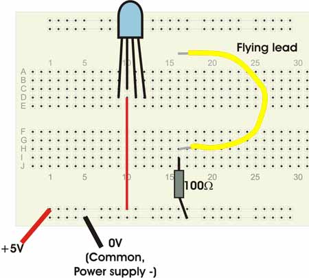
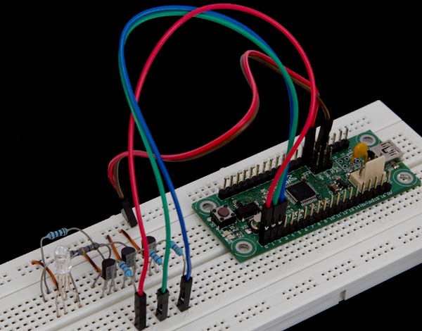
Study the breadboard layout above. Assuming I have correctly connected the common anode pin to +5V via the red wires, then touching each of the other pins with the yellow flying lead should light up one of the LEDs and identify the colour for that pin. Try it yourself! If you don't get the expected result, try a different pin as the common. I did this work with a sample LED from a supplier, which came with an ambiguous pre-release data sheet. In the end I was getting confused and wound up drawing this diagram:
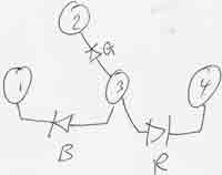
Make yourself a sketch that will help you remember which pins are R, G, B and A-for-Anode.
If you can't make sense of it whichever pin you use as common, try reversing the power supply feed. If you can make it make sense that way, you have a common cathode LED, which can't work in the EasyStep.
Identify the transistor pins
Click here for instructions for identifying the transistor pins. Click again to close.
The transistor pins, Base, Collector and Emitter. Different transistors have different pin placements - the manufacturers like to keep us on our toes! Here are the pinouts for the two types I have suggested. You can see that one is a complete 180° rotation of the other!
Whatever transistors you have, get hold of its data sheet and find the pinout diagram. Note that sometimes they give a bottom view. Mixing top and bottom views can ruin your day, so take care.
Wire the breadboard
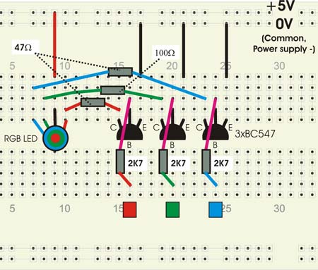
Now that you know the pinouts of the LED and the transistors, you can wire up the breadboard with the confidence of knowing that you won't have any mistakes due to a lack of information. Wire up the components as shown on the diagram. Make the necessary adjustments for the pinouts of your LED and transistors. Just follow the letters (B, E, C) and the colours.
Bench test the electronics
Before connecting to the EC1 we are going to test the LED driver on its own. To do this you need a 5V power supply. The easy way to get one of those is off your EC1, plugged into the USB on your computer.
Use two male-female jumper wires. Locate a +5V pin on the EC1 and wire it to the +5V rail on the breadboard, then locate a 0V pin on the EC1 and wire it to the 0V rail on the breadboard.
Caution: Be very careful that the wire with +5V on it touches nowhere but the terminals marked with coloured squares. Anywhere else could result in excessive smoke emissions and component failure.
Make sure the EC1 has power. Now take a piece of wire and connect it between +5V and the terminal labeled with a red square in the diagram above. The LED should light up red. If that fails, double check your connections, the power polarity etc. The LEDs on the EC1 can serve to indicate that it has power. If neither of the LEDs on the EC1 is on, it means either it has no power or does not contain a program that turns on either LED. To get a power indicator, disconnect the power from the breadboard then go back and complete this EasyStep, which will get you some LED action on the EC1 if it has power.
The test all 3 colour channels.
So what's happening here?
When you connect the "free" end of a 2K7 resistor to +5V, a small (positive) current flows into the base of the transistor. This turns on the transistor so its collector and emitter become very nearly shorted to each other inside. That means the resistor that connects to the LED suddenly has one end connected to 0V, which is exactly what we did to it earlier on when we were testing the LED pinouts. Result: The LED lights up.
Manually manipulate the RGB LED from your PC
Once you know the breadboard is working, the next step is to manually control the RGB LED from SPLat/PC. This will not only move you one small but significant step closer to the goal, but also be an opportunity for learning.
- Plug the EC1 into your computer, launch SPLat/PC, and connect to the EC1. See this EasyStep.
The Module window should look much like this:
- Wire from pin 0 of the EC1 to the red input terminal (red square) on the breadboard
- Wire from pin 1 of the EC1 to the green input terminal on the breadboard
- Wire from pin 2 of the EC1 to the blue input terminal on the breadboard. Here's my setup at this point (except it's not wired to the computer):
- Open the analog window from the Window menu on SPLat/PC. It should look something like this:

- Type 100 into the Output 0 box, and hit return. The LED should light up red;
- Play with all 3 colours.
So what's happening here?
The LED driver transistors are being controlled from 3 outputs of the EC1. These outputs are called PWM (Pulse Width Modulated). What they do is generate a rapid stream of pulses whose duty cycle (on/off ratio) can be varied. At 100% duty cycle the output is permanently on. At 0% duty cycle the output is solidly off. At 50% duty cycle it is on exactly half the time.
The analog window controls that percentage. The number 255 corresponds to 100%.
When the LED is driven by this PWM signal, it is flashing on and off very rapidly, so rapidly that your eyes have no chance of registering the flashes. All you see is the average light level. The higher the duty cycle, the brighter the light. By applying different duty cycles to the 3 LEDs, we get different colour mixes.
Later, in the program, we will be controlling the same outputs not with an integer number between 0 and 255, but with a floating point number between 0.0 and 1.0.
What the SPLat program does
The sample SPLat program given below repeatedly cycles all three colours through the full range of intensities. It cycles each colour at a slightly different rate, so eventually it will pass through every possible permutation.
To run the program
Now you know your electronics are working you can download the program, confident in the knowledge that the hardware is all in order. (just don't bump anything out of place!). Follow these steps and you will soon have some nice colour effects to show your Significant Other.
- Close all running copies of SPLat/PC
- Click this link to download the program and launch it into
SPLat/PC. Depending on what browser you are running, you will need to select the appropriate option to run the file in the matching application (SPLat/PC).
Once the program is loaded into SPLat/PC, the edit window should look something like this:

- Connect SPLat/PC to the EC1. Details.
The Module window in SPLat/PC should now look something like this:
- Hit CTRL+F12 to translate the program and send it to the EC1 and run it.;
The program
The full program is listed below, with extensive annotations. To show/hide the program listing click here. There are pop-ups for each major functional block of code, and clickable links on individual instructions that take you to the formal descriptions of the instructions.
The block annotations are marked like this:
;[...]Place your mouse over that line to see a pop-up describing the overall logic of the block.
Many instruction also have clickable links to the formal definition online. (Tip: Click the link with your mouse wheel to open in a new browser tab)
Please invest some time studying the program. Even if you don't understand all the details, try to at least get the general drift of what the major blocks are all about.
;======================= Driving an RGB LED with an EC1. ================================
; This assumes an RGB LED interfaced to analog (PWM) outputs 0, 1, and 2, which just
; happen to be the same pin numbers.
;[...]
;Define the outputs
aoRED           EQU     0
aoGRN           EQU     1
aoBLU           EQU     2
;[...]
;Define the 3 delays
tRedDelay       EQU     2
tGrnDelay       EQU     3
tBluDelay       EQU     4

;Let's just make 3 tasks that cycle the LEDS at slightly different rates. This will
;cover the whole gamut of the LED.
;[...]
                LaunchTask      tskRED
                LaunchTask      tskGRN
                LaunchTask      tskBLU
                RunTasksForever
;--------------------------------------------------------------------
;[...]
tskRED:
RedGoUp:   ;In this loop we are incrementing the red channel. The actual value is held in the W register
                Pause           tRedDelay       ;Delay
                fLoadQ          0.01            ;The amount we will increment the output by
                fAdd                            ;Add the 0.01 to W
                fLoadQ          1               ;The maximum value we are allowed
                fGoIfWgtQ       RedGoDown       ;Jump if W > Q, meaning we hit the high limit
                fAnOut          aoRED           ;Output the new value
                GoTo            RedGoUp         ;Loop back and repeat

RedGoDown: ;In this loop we are decrementing the red channel. The actual value is held in the W register
                Pause           tRedDelay
                fLoadQ          -0.01           ;We will increment the output by a negative amount, i.e. decrement it
                fAdd                            ;Add the -0.01 to W
                fGoIfNeg        RedGoUp         ;Jump if W went negative
                fAnOut          aoRED           ;Output the new value
                GoTo            RedGoDown       ;Loop back and repeat

;--------------------------------------------------------------------
tskGRN:
GrnGoUp:
                Pause           tGrnDelay
                fLoadQ          0.01
                fAdd
                fLoadQ          1
                fGoIfWgtQ       GrnGoDown
                fAnOut          aoGRN
                GoTo            GrnGoUp
GrnGoDown:
                Pause           tGrnDelay
                fLoadQ          -0.01
                fAdd
                fGoIfNeg        GrnGoUp
                fAnOut          aoGRN
                GoTo            GrnGoDown

;--------------------------------------------------------------------
tskBLU:
BluGoUp:
                Pause           tBluDelay
                fLoadQ          0.01
                fAdd
                fLoadQ          1
                fGoIfWgtQ       BluGoDown
                fAnOut          aoBLU
                GoTo            BluGoUp
BluGoDown:
                Pause           tBluDelay
                fLoadQ          -0.01
                fAdd
                fGoIfNeg        BluGoUp
                fAnOut          aoBLU
                GoTo            BluGoDown
Some additional notes
- You may have noticed I used 100Ω for green but 47Ω for red and blue current limiting resistors. The reason is that in all the RGB LEDs I checked out, the green output is about twice the other two colours at the same current.
- You can stock up on a huge range of resistors for less than a cent each here.