MMi203: Making external connections
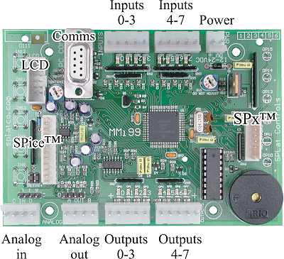
The above picture shows all the connectors used for making external connections to the MMi203 and its predecessors. Moving clockwise from the top these are:
Inputs 0-3 and 4-7
There are two 5-pin connectors for external digital inputs. Each connector has 4 signal pins and one common (ground). The wiring for these is detailed under MMi203 external digital inputs.
Power
This 2-pin connector is for applying power to the MMi203. The wiring and power supply requirements are described under MMi203 Power supply.
SPx
The SPx expansion scheme is documented elsewhere in the SPLat Knowledge Base.
Outputs 0-3 and 4-7
These two 5-pin connectors are for the 8 external outputs. Each connector has the positive power supply pin brought out. The use and wiring of these is detailed under MMi203 external digital outputs.
CAUTION: Take care never to short an output pin to the positive common pin. If the output is on at the time you will blow up the output chip instantly!
Analog out
This 4-pin connector is for the 2 analog outputs. There are 2 signal pins and 2 ground wires. The use and wiring is documented under MMi203 external analog outputs.
Analog in
This 4-pin connector is for the 2 analog inputs. There are 2 signal pins and 2 ground wires. The use and wiring is documented under MMi203 external analog inputs.
SPice
This connector is for low cost SPice add-on boards. Normally you would simply plug a compatible board onto this connector. Some information about the connector is provided under MMi203 SPice connector.
LCD
The LCD connector supports a character Liquid Crystal Display.
Comms
This connector is for communications to a PC either directly or via a modem. The various uses are documented in many places throughout the SPLat Knowledge Base. You will find an overview under MMi203 Comms connector.