HMI430/700: Digital inputs
To use a bidirectional digital I/O point as an input you must make sure that the corresponding output is OFF. That is the case when the controller is first powered up, so all I/O points are inputs on power up.
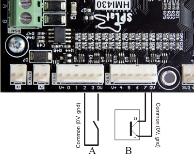
In the picture A is a simple switch connected to input 2. When the switch closes, it connects input 2 to circuit common, turning the input on.
B is the output of an NPN style sensor connected to input 7. The sensor would also require a positive supply voltage to power it and this can be sourced from the "V+" terminal. See the manufacturer's data for connection/operating voltage details of the sensor you are using. The terminal on the sensor labeled with a minus sign above will be the manufacturer's designated negative or common terminal, and the "O" terminal will be the designated output terminal of the sensor. When the sensors NPN output transistor turns on, the input is activated.
As an input, an HMI430 digital I/O pin responds to a connection to 0V. If the input pin is connected to 0V, it is interpreted as being ON, and when read by your program will give a True value. For example, the instructions
 Input 5
 GoIfT SomeWhere
will transfer program control to the line labelled "SomeWhere" if the pin for input 5 is connected to 0V either through a piece of wire, a switch or an NPN sensor.
So how close to 0V must it be?
That's a good question, glad you asked! The input circuits have a certain "threshold voltage". Due to chip variations this is a somewhat rubbery number. The specification page defines "Digital input low" and "Digital input high" voltages. To guarantee the input is seen to be ON it must be below the former, to be seen as high it must be higher than the latter. The range in between is a "no man's land" where we can't be sure what will happen.
Input current
When connected to 0V (i.e. ON) the inputs will drive (source) a small amount of current through the external circuit. This current is listed in the specification as Digital input current. This current is important because it contributes to contact wetting.
Input debounce
One of the things we do in SPLat controllers is automatically debounce the inputs. Here's how this works:
When a metal contact, like a relay, closes, it may (usually will) bounce open and closed a few times. This could cause havoc in your program, if it's not allowed for. So what we do is that in the majority of input instructions we filter out the bounce with some special code in the firmware. The result is to eliminate the levels of contact bounce that would normally occur in regular relays and switches.
A side effect is that input changes are delayed for 10-20mS.
If you don't want the debounce, there are some input instructions that do not debounce the inputs, such as InputF and InputFM