SX10504: Connecting to your controller
The board can connect to your controller in one of two ways: Via the 2 pin TTL Xwire connector or via an RS485 adaptor, if your controller does not have an RS485 Xwire interface. You have to decide which interface you are using, select it via a jumper and then connect to the corresponding external terminals.
Xwire is our proprietary serial peripheral bus. It consists of the Xwire electrical interface and the Xwire data protocol that is used to convey data across the interface and wiring. The 2 pin TTL Xwire electrical interface is good for a few feet and up to 10 boards. The final choice of interface is dependent on the distance and the electrical environment (ie: the amount of electrical noise).
RS485 is an industry standard electrical interface suitable for direct wire connection between devices located up to hundreds of feet apart. RS485 will allow up to 32 boards to be connected. The programming is the exactly same but you will be able to go further for the cost of an extra RS485/Xwire converter on the controller. The RS485 interface is more forgiving in terms of noise and is better protected against electrical transients.
Selecting the Xwire or RS485 interface

A 3-pin jumper in the middle of the board is labelled 'RS485 X'. Inserting a jumper in the two pins labelled RS485 will activate the RS485 interface. Inserting a jumper in the two pins labelled X will activate the Xwire electrical interface.
Connecting to the Xwire interface

Two connectors on one side of the board are labelled X1 and X2. These are the TTL Xwire electrical connections. The two connectors are wired in parallel on the board to facilitate daisy chaining, and are completely interchangeable. The left-hand pin of each connector is ground (0V). If you are wiring to other boards with X1/X2 connectors, simply wire like pins together. If wiring to MMi202 or SL100, see the Xwire connection instructions in their documentation. See also wiring in the Xwire documentation.
Connecting to the RS485 interface
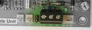
The 3-pin screw terminal block is for RS485 connection. The A and B terminals should go to A and B on all other devices on the RS485 system. The G terminal should go to system ground. Just next to the terminals (to the left above) is a jumper marked "Term". Installing a jumper in that position provides an RS485 line terminator.
Connecting to the conductivity channels

The ten pin connector to the bottom right of the board is for connecting your electrodes. The channels are labelled C1-C5. There are two pins per channel, one for the active electrode (numbered with the channel number) and one for a ground (0V) connection. All 0V pins are connected together on the board and to the 0V power supply pin on the host controller board. The electrodes, and the use of the 0V connections, are explained in SX10504: About water level detection.
Sensitivity adjustment
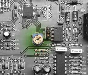
The POT in the centre of the PCB is the sensitivity adjustment. It controls the sensitivity on all conductivity channels at the same time.
Analog inputs
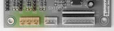
The three 2-pin connectors at the bottom left of the board are the three 10 bit analog inputs. The analog input channels are labelled I0-I2. Associated with each analog channel is a set of four configuration pins. An input is configured by using one of the supplied jumpers to bridge certain pins on the "TIV"connector. Explained in detail in SX10504:Analog Jumper Configuration.
Analog outputs
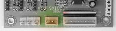
The four pin connector to the bottom centre of the board is the two 10 bit analog outputs. The analog out channels are labelled O0 and O1. Each analog output has a voltage range of 0V - 10V, and can source a maximum load current of 5mA (2Kohm load).