SX10504: Analogue channel jumper configuration
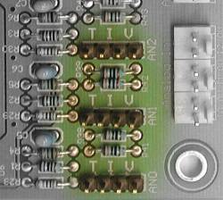
The picture above shows the connector used for analog inputs, and the associated configuration pins. An input is configured by using one of the supplied jumpers to bridge certain pins.
There are three analog input channels on the SX10504 board. Each input can be configured to operate on 0-10V, 0-20mA or as a temperature measuring input (using an external thermistor sensor). In all cases the input uses one input pin and one common pin. The common pins on the analog input connector are tied to the board's 0V terminal. Please see the article on common terminology for an explanation of the 0V terminal.
The three analog inputs are designated as I1, I2 and I2. Each channel has a 4-pin configuration jumper field. A single jumper (shunt) on a pair of jumper pins selects the operating mode (V=voltage, I=current or T=temperature).
Using voltage mode
To use an analog input in voltage mode you set its jumper to bridge the two pins either side of the letter V and apply the input voltage between the input (positive) and the common (most negative). If Xwire has been successfully configured the analog channel data will appear in the memory locations of the Xwire receive data block as a normalized floating point number in W which ranges from 0 at 0V in to 1.000 at 10V in. The range 0 to 1.0 is divided into 1023 steps of 0.00097752.
In voltage mode the input resistance is 200KOhm. The accuracy is about 1.5% of full scale and resolution is 10-bit or 0.1% of full scale (8-bit/0.4% on older models). There is an input noise filter comprising a single RC time constant of 5mS.
If you leave the jumper out, you will get a 0-5V range instead of 0-10V.
Using current mode
To use an analog input in current mode you set its jumper to bridge the two pins either side of the letter I. You then feed the current to be measured into the input pin, with the return out of the common pin. The current source (e.g. 4-20mA transmitter) must be of the type that sources a positive current from its output pin and sinks (returns) the current into its ground (or minus out) pin. Most 4-20mA transmitters have an isolated output, in which case you connect the positive output of the transmitter to the analog input of the SX10504 and the negative output of the transmitter to the common pin on the SX10504.
If Xwire has been successfully configured the analog channel data will appear in the memory locations of the Xwire receive data block as a normalized floating point number in W which ranges from 0 at 0mA in to 1.000 at 20mA in. The range 0 to 1.0 is divided into 1023 steps of 0.00097752.
In current mode the input resistance is 250Ohms. There is an input noise filter comprising a single RC time constant of 10mS.
Accuracy and resolution (voltage and current modes)
The accuracy is about 1.5% of full scale. Resolution is 10-bit (0.1% of full scale).
Using thermistor mode
To use the analog input in temperature mode you set its jumper to bridge the two pins either side of the letter T and connect a suitable thermistor between the analog input pin and common. There are two basic types of thermistor: Positive Temperature Coefficient (PTC) and Negative Temperature Coefficient (NTC). The latter, NTC, is the type used for temperature measurement with SPLat. Typically, an NTC thermistor is specified as having a certain resistance at 25 degrees C.
The adjacent diagram shows the thermistor measuring circuit.
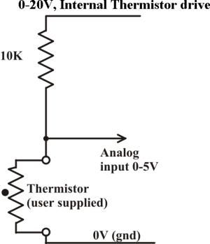
The thermistor is the bottom resistor in a voltage divider. The top resistor is a fixed on board 10.25KOhm resistor. The voltage divider is driven by a programmable voltage set by a floating point number stored to Xwire memory location 8-11 as a number 0-1. The thermistor drive voltage can be set to anything between 0V and 20V. Note that the board supply voltage must be at least 2V greater than the intended drive voltage. With this memory set to 0 it will result in a 0V drive, with this memory se to 1 it will result in 20V drive.
In this thermistor mode the full scale analog input voltage is 5V.