HD8: Connections
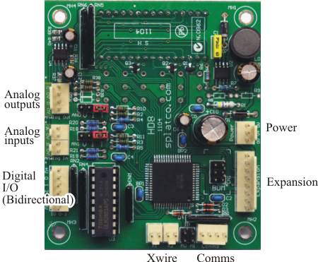
The above picture shows all the connectors used for making external connections to the HD8 These are:
Bidirectional digital I/O
This is a 6-pin connector for the 4 digital I/O points, which can each be used as an input or an output. The connector has 4 signal pins as well as connection to the positive supply voltage and to common (ground). The wiring for these is detailed separately for input mode and output mode.
Analog inputs
These two 2-pin connectors are the analog inputs.
Analog outputs
A 4-pin connector for two analog outputs.
Power
This 3-pin connector is for applying power to the HD8. The wiring is described under HD8 Power supply.
Comms
This is the connector you connect to for programming the HD8. This is NOT an RS232 connector. A PC232 programming cable adaptor is required for connecting to a PC for programming.
Expansion
This connector is for expansion boards like the XBIO16. The SPx expansion scheme is documented elsewhere in the SPLat Knowledge Base.
Xwire
Xwire bus connections. The two connectors are identical and wired in parallel. The lefthand pin as shown is 0V (ground). The righthand pin is bidirectional serial data.
Analog inputs
These two 2-pin connectors are the analog inputs.
Analog outputs
A 4-pin connector for two analog outputs.