HD8: Power supply
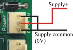
The above illustration shows the power connections to the HD8. We have used a 3-pin connector, to differentiate from 2-pin connectors used elsewhere on the board. There are two pins for 0V (gnd, common). You do not have to wire both to both 0V pins; either one will do. The wire shown in red above should go to the positive terminal of your power supply. The black wire should go to the ground or common terminal of the power supply (often labelled minus on a single voltage supply). See also 'Some common terminology':
Supply voltage
In general, the HD8 needs a supply voltage between 10VDC and 24VDC. The voltage is allowed to go to a maximum of 32V. Note that the HD8 operating temperature ratings depend on the supply voltage.
It's quite OK to use an unregulated power supply. Just remember that the ripple will make the voltage instantaneously less than the average DC value, and the board will respond to the instantaneous value. Remember, too, that an unregulated supply can go quite a bit higher than its nominal value, especially when lightly loaded and if the mains voltage is high. In general we suggest you use a 24VDC switchmode power supply. These are now so inexpensive that there is little reason not to use one.
Supply current
The current drawn by the board will depend on the supply voltage and what the board is doing. The maximum supply current draw versus supply voltage is:
| Supply voltage | Current |
|---|---|
| 10V | 66mA |
| 12V | 56mA |
| 15V | 47mA |
| 18V | 42mA |
| 24V | 37mA |
| 28V | (36mA) |
| 32V | (36mA) |
These figures are based on everything being on at once. The figures do not include any external loads such as relays. The HD8 uses an onboard switchmode voltage regulator, which is why the current actually decreases with increasing supply voltage.
Note: Figures at 28V and 32V are given for reference only. We do not recommend operating the board at voltages over 24V for sustained periods of time. The board can be damaged if the power supply voltage goes over 32V, even momentarily.