MBIO16: Power requirements
Because the MBIO16 can potentially carry quite large currents (up to 32A peak) it is important to take special care with the power supply wiring.
The MBIO16 board may be powered off the same power supply as the SPLat controller board it serves, or off a different supply. However, it is very wise to run separate power wires for controller and expansion boards. The MBIO16 requires a supply voltage of 10-28VDC, with an absolute maximum rating of 32VDC. It typically draws less than 20mA plus whatever current is flowing through the I/O pins, plus about 5mA per illuminated LED (at 24V, proportionally less at lower voltages).
Note: If you use two power supplies, the expansion board(s) must be powered up at the same time as, or before, the controller.
It is absolutely essential that none of the current from the external loads or inputs flows through the cable back to the controller. For this reason 0V on the MBIO16 must be wired independently back to the main power supply. If you use separate power supplies you must tie their negative (0V) terminals together and to the 0V terminals of the controller and MBIO16. If you fail to do this you will at best experience erratic performance and at worst damage either the MBIO16, the controller board or both.
You can supply power for the board itself via the quick connect tabs labeled 0V and +V and located at either end of the row of LEDs. Note that the + pins on the I/O connectors are joined together on the board and connected to the +V tab, similarly for the 0V pins. It is a good idea to separately wire all 0V pins back to the power supply common. You can use the +V tab to power the board, and then use the + pins on the I/O connectors to feed power to the loads.
Wiring arrangements
The following diagrams show some different possible connection schemes for output loads and power, with emphasis on the power supply feed. Which scheme you use will depend on what is most convenient for wiring and on the load current(s) you are running. In these diagrams the loads are represented by generalized rectangles. Finer detail for various load types is provided elsewhere. Just remember that the load (relay coil or whatever) goes between the board's I/O pin and the positive supply.
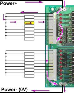
In the first diagram, above, the power is fed to the MBIO16 via the quick connect tabs labeled V+ and 0V (thick lines). The loads get their positive connections off the V+ pins on the I/O connectors (which are fed from the V+ quick connect tab via the board). The 0V return is taken off the 0V quick connect tab. The pink arrows indicate the path the load currents will follow. The total load current flows through the quick connects.
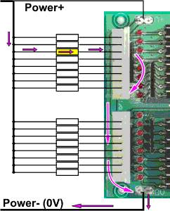
In the next diagram, above, the V+ common for the loads is run external to the board. A wire is still run to the V+ quick connect tab, to provide power for the board itself. That wire will only carry low current. The total load current flows out of the 0V quick connect tab.
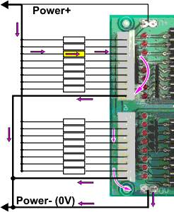
In the final diagram we have run 0V return wires from the 0V pins on the two I/O connectors, as well as out of the 0V quick connect tab. This provides a lower resistance, redundant path. How the current divides between the 3 possible paths depends on wire and contact resistances. In practical terms it is impossible to predict the split, but having multiple paths is definitely advantageous.
Why would you use separate power supplies?
The output circuits on the MBIO16 contain clamp diodes connected to the + supply pin. These are there to prevent damage when switching inductive loads like relay coils. Under Connecting output devices you will find a diagram of how an inductive load is connected (load B, with a parallel diode). The diode on that diagram is replicated on the board (we still recommend an external diode to reduce switching noise). The diode must be connected to the same + supply as the load. For that reason, the MBIO16 + supply pin must be connected to the same power supply as the load (even if you are driving non-inductive loads).
If, for any reason, you need to power the controller off a voltage other than that driving the loads on the MBIO16, you can use two different power supplies providing you observe the above rules.
Wire gauges
The currents that can potentially flow in and out of an MBIO16 board are high - high enough to over-heat connecting wires. In order to avoid a fire hazard, all wires connected to the MBIO16 should be rated at equal to or greater than the current limit or fusing level of the power supply. It is your responsibility to comply with all relevant wiring rules in your locality. Disclaimer.