OBQC: Theory of operation
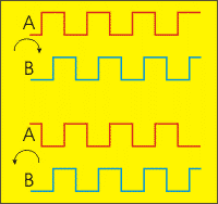
A quadrature encoder is an incremental encoder that generates two output signals that are offset from each other. The signals are usually called A and B. In the above diagram you can see the A and B signals for clockwise encoder rotation (top) and counterclockwise encoder rotation (bottom). You will notice that in the top diagram a given transition on A happens before the same transition on B (A leads B). On the bottom diagram A lags behind B. The amount of lead or lag is 1/4 of a cycle (90 degrees), which is why the term quadrature encoder is used.
Because of the two quadrature signals it is possible to determine not only how far the encoder has moved or rotated, but also the direction. The encoder is called incremental because it does not provide information about the absolute position or angle, only about changes (increments). To know exactly where the encoder is you have to count pulses from a known starting point.
The OBQC function on a SPLat controller board tracks two nominated inputs (which inputs is documented for each product) and maintains a count in a 24-bit up/down counter. The value in the counter can be accessed via the floating point register W. The counter can be cleared, set to a given value and read out.
A 24-bit counter has a capacity of 16,777,216 counts. In SPLat that is treated as a signed number in the range -8,388,608 to +8,388,607. If one count represents 0.01mm (0.0004 inches) the range is +/- 83m or 272 feet. If the counter hits the maximum count it wraps to the minimum count, and visa versa. Given the range, that should not happen unless something has gone wrong in your machine or your program.
A mechanical computer mouse contains two quadrature encoders, one for X direction and one for Y direction. If you have an old mechanical mouse lying about it can be educational to pull it apart and analyze how the encoders work. It is sometimes possible to make your own encoder using photoelectric or proximity sensors and a convenient target such as a cog wheel or disk with holes cut in it. If you do so, remember it is crucial that the on and off times are very close to equal and that the two channels have the correct offset from each other.
The OBQC counts on each input transition, so it will accrue 4 counts per complete cycle of the inputs. There is no point trying to specify which connection and rotation will count up or down. This is best determined by trial and error on your prototype. If it counts in the wrong direction just swap the inputs.
A quadrature encoder doesn't have to be a rotary device. If is perfectly possible to make a linear motion encoder using the same principle.