The FP16 can be set for use in NPN or PNP input modes. "NPN" and "PNP" refer to two ways of electronically switching an on/off signal out of a sensor circuit. Many electronic sensors, like proximity switches, are available in both types or able to be set for one mode or the other. Think of NPN as "Negative switching" and PNP as "Positive switching". We prefer to talk about 0V or common rather than negative - see "Common terminology".
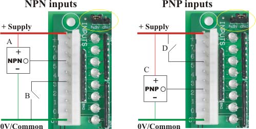
The above picture shows the input connector being used with NPN (left) and PNP (right) input connections. Note that the jumper circled in yellow must be set to the desired mode. It sets all 8 inputs at once.
The picture shows an NPN type sensor 'A' with its output connected to the board's input 5. When the sensor is off, its output is an open circuit. When it turns on its output pin gets internally connected (through an NPN transistor) to its negative supply pin (our 0V or "common" line).
'B' is an ordinary switch, say a mechanical limit switch connected to input 3. In NPN mode it must be connected between the input pin and the 0V pin.
In NPN mode the input indicator LEDs will light up red when the input is on.
The picture shows an PNP type sensor 'C' with its output connected to the board's input 2. When the sensor is off, its output is an open circuit. When it turns on its output pin gets internally connected (through a PNP transistor) to its positive supply pin (which is also our + supply line).
'D' is an ordinary switch, say a mechanical limit switch connected to input 5. In PNP mode it must be connected between the input pin and the + supply pin.
In PNP mode the input indicator LEDs will light up green when the input is on.
In PNP mode your SPLat program will see the inputs as inverted. An ON input gets read as OFF, and an OFF input gets read as ON. Your program must make a suitable adjustment.
A current will flow through the board's input pin in the ON state. The magnitude of the current depends on the supply voltage. Assuming a dead short between the input pin and 0V (NPN mode) or + (PNP mode), the current is given by the equation
I(in) = (V(supply) - 1.8V) / 4700
The 1.8V represents the voltage drop of the input indicator LED. The 4700 represents the input pullup (NPN) or pulldown (PNP) resistance.
This equation translates to about 2.1mA with a 12V supply and 4.7mA with a 24V supply. This is low enough to be compatible with off-the-shelf sensors.
Take care when driving the inputs from switch or relay contacts. The problem is "contact wetting" (or a lack of it) and due not to too much current but to too little current. You should select contacts that are designed for low level switching, which invariably means gold plated. There is an article about this here.
The input threshold is the voltage at the input pin where the board switches between on and off conditions. Typically this is 6V for the FP16. In practice the threshold voltage of the input is related to the threshold of the input chip, which has fairly wide uncertainty. Due to this uncertainty the input threshold can be anywhere between 3V and 9V. The range between 3V and 9V is a "no man's land" where behaviour is not guaranteed. That means that you may determine experimentally that something works OK on a prototype, but that gives you no right to assume it will therefore work on all future units.
Note that the threshold voltage varies from product to product. Please check the specific documentation on the board(s) you are using.