MS120: Operator interface
The MS120 has a built in operator interface (Man-Machine interface). The operator interface consists of:
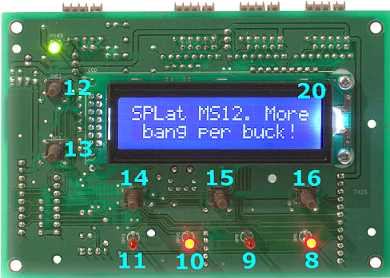
5 push buttons
These are miniature momentary action push buttons, wired to dedicated inputs. They are sensed by a program just like any other input, though the SPLat programming language contains special instructions that are designed to simplify programming user interface operations. The buttons appear to your program on inputs 12 through 16.
4 LEDs
These are program-controlled front panel indicators. They are programmed like any other output. There is one pair of instructions for making it extremely easy to make them blink (flash). The LEDs appear to your program as outputs 8 through 11.
Liquid Crystal Display
The liquid crystal display, when fitted, is programmed according to the documentation for the "On-Board LCD". The LCD backlight is on/off controlled by output 20. It can also be dimmed in MS120 boards with the latest Firmware. Output 20 is shared as one of the pins of the second SPice connector (it also appears as input 25), but cannot be used as such on boards fitted with an LCD.
The backlight uses white LED technology, which is a technology with a lifetime of about 3000 hours. Your program should turn off or dim the backlight when not in use, especially in applications that are turned on 24/7. Example code for doing this is provided in Example LCD backlight auto-off timers.
Faceplate and graphic overlay (you supply)
The MS120 is designed to be mounted behind a flat faceplate. The plate has cutouts to match the buttons, LEDs, and if used, LCD. You will find dimensioned drawings in the files resources area of the resources CD or on our file resources FTP site. The board needs to be spaced off the faceplate so the tops of the push button switch stems fall minutely (<0.1mm) below the outside surface of the faceplate. You then place a flexible polyester or Lexan graphics overlay on the outside surface and the buttons can be activated by pressing them through the overlay. You can see more detail in the MMi202 documentation.
Warning: The board and the metal faceplate (or any other metallic surface that the board is mounted to) must be attached using metal screws and no insulating hardware so they are at the same potential. The mounting holes on the board are deliberately made with exposed metal. Failure to "bond" the face plate to the board will expose the board and the LCD to the risk of damage from static discharge.