This EasyStep will show you the basics of driving an RC (hobby) servo motor off an analog (PWM) output.
RC servos are so called because they originated as the actuators in Radio Controlled model aircraft. Early radio systems would use a number of tone frequencies, one per control function, and transmit timed pulses of tone to the aircraft. In the aircraft a number of separate tone detector circuits (often based on LM567 chips) would separate out the pulses and feed them to servo mechanisms designed to respond to pulse width.
What you will need
- An EC1 all ready to plug into your PC via USB;
- Firmware V4.7 or later in the EC1;
- SPLat/PC installed and running, and the basic skills to enter and download programs;
- A hobby servo. I did this with a Power Pro Micro Servo 9g, which cost me the princely sum of $3 each (here);
- (optional) A 4.5 to 6V power supply.
Basic servo theory
The video clip shows how pulse width affects the position. The program for this is given at the end of this EasyStep
An RC servo is a small motorised device that will rotate to a position determined by an input signal. It has 3 wires. 2 wires are for power (typically 4.5V to 6V, corresponding to 3 or 4 typical primary cells). The third wire is for the position control signal. The signal is a train of pulses. The width (duration) of the pulses determines the angular position the servo will seek. The repetition frequency of the pulses is generally 50Hz, i.e. one pulse every 20mS. The pulse width can range between 0.5mS and 2.5mS for the servo I used. Other servos may use other pulse widths. An often quoted figure is 1mS to 2mS (1.5mS±0.5mS) for 90° rotation. The servo I used has 180° rotation, so its 1.5mS±1mS makes sense.
 |
Sketchily drawn waveforms with two different pulse widths |
Expect unit to unit variations in the angle versus pulse width behaviour — these are very cheap and you can't expect them to be very consistent!
Note that it is the width (duration, in mS) of the pulses that matters, not the duty cycle (percentage of high time vs total period). The SPLat fAnOut instruction uses duty cycle, so we have to calculate the duty cycle that will give the required pulse width.
Connecting the servo
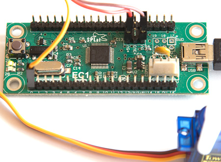
The servo has 3 wires. The colours can vary between brands. There will generally be a red wire, which is the positive supply voltage. The 0V supply (ground, negative) will generally be an "earth" colour, like brown (as on mine) or black. The control signal is typically yellow. There is a very good guide here.
To make it easy to connect to the EC1, I replaced the 3-pin plastic housing that came on the servo with three separate 1-pin housings taken from M-F jumper leads. In both cases the metal insert was held in place by a fine plastic tab. I used a pin to gently lift the tab and slip the metal contact inserts out.
The photo below shows the connections to the EC1. For a single servo the power for the servo (red wire) can be taken out of a +5V power out pin on the EC1. The servo ground (0V, negative) wire (brown on my servos) goes to a 0V pin on the EC1. For this EasyStep the PWM control signal (yellow wire) comes from the Analog Out 0 pin of the EC1. The "analog outputs" of the EC1 are actually pulse width modulated (PWM) digital outputs. Click here for more details on that.
The simplest driver program
The following program will drive the servo back and forth across its full 180° range. You can modify the end points by changing the target pulse widths (given in mS)
;This is an absolute bare-bones program to jiggle the servo between two extremes.
;The PWM base frequency is set to 50Hz, thereafter the servo pulse width output is
;alternated between 0.5mS and 2.5mS. Those correspond to the full 180' span of the
;cheap-as-chips ($3) Power Pro Micro Servo 9g I am playing with.

;====== Set PWM base frequency =======
;The 40kHz default PWM frequency is far too high for a servo. Configure it to 50Hz,
;which is the accepted "standard" for RC servos.

SetPWMBaseFrequency:  ;Documented here
        SetU            0,8
        SPxCmd1         0,!CPU ;Don't try to understand this bit of code if you are new to SPLat. Just trust me, and use it with joy.

;======= Continuously jiggle the servo between two extremes
Jiggle:
        fLoadW          0.025                ;Load W floating point register PWM duty cycle required for 0.5mS
        fAnOut          0                    ;Output to the servo
        Pause           100                  ;1S delay
        fLoadW          0.125                ;PWM duty cycle required for 2.5mS
        fAnOut          0
        Pause           100
        GoTo            Jiggle
The duty cycle figures are calculated as:
fAnOutValue = Required Pulse width in mS * PWM base frequency / 1000
Example:
Say I want a 1.5mS pulse (about mid-range)
fAnOutValue = 1.5 * 50 / 1000 = 0.075
Feel free to edit the numbers 0.025 and 0.125 for other target servo positions.
More than one servo (or a bigger servo)
It is only possible to draw 400-500mA out of the 5V power out pins on the EC1. We deliberately include a 600mA current limiter in the EC1, to give your computer some measure of protection against bad things happening to the EC1. There is enough capacity there for one small servo, but for more servos or bigger servos you need an separate 5V (or so) power supply.
The following diagram shows the connections for an external power supply for large or multiple servos. The dotted red line shows how you would supply power to the EC1 from the same power supply only if you are not powering it from your computer via the USB cable.
Note: Do not allow an external power supply to power the EC1 while it is plugged into your computer. The result of doing that could be serious damage to the computer.
The YouTube demo program
The program used in the YouTube clip at the top of this page is more elaborate. You can use it to study a few programming techniques.
;Driving a servo:
;This is the program used for the YouTube demonstration of the effect of different pulse widths.

iButton         iEQU    0               ;The EC1 onboard button
oGreenLED       oEQU    0
aoServo         EQU     0               ;The servo output, masquerades as an analog output (actually PWM)

kPWMSetting     EQU     8               ;These are the index and table values from
kfPWMPeriod     EQU     20              ;mS

fMinPulseWidth  defFLOAT                ;Stores the minimum pulse width in mS
fMaxPulseWidth  defFLOAT                ;Stores the maximum pulse width in mS

        GoSub           SetPWMFrequency50  ;Set the PWM base frequency to the 50Hz wanted for servos.
        GoSub           SetMedium        ;Initialise the min/max pulse width values
        LaunchTask      tskJiggle       ;The main task, which "jiggles" the servo to and fro
        LaunchTask      tskHeartBeat    ;Flashes a LED
        LaunchTask      tskSequencer    ;Changes the min/max servo pulse widths
        RunTasksForever

;====== Task that "jiggles" the servo between two pulse width settings ==========
tskJiggle:
        fRecallW        fMinPulseWidth     ;Minimum mS required
        LaunchTask      tskPWMOut          ;This converts to a duty cycle value and sends to the servo output
        Pause           100                ;1 second
        fRecallW        fMaxPulseWidth     ;Maximum mS required
        LaunchTask      tskPWMOut
        Pause           100
        GoTo            tskJiggle          ;Repeat forever

;====== Set PWM base frequency to 50Hz =======
SetPWMFrequency50:
        SetU            0,kPWMSetting
        SPxCmd1         0,!CPU
        Return

;======  Calculate the duty cycle value required to get the pulse width (mS) value in W ======
;Returns its result in W, so effectively converts W from a mS pulse width to duty cycle.
;This takes into account the PWM base frequency (expressed as the inverse, period)
PWMCalc:
        fLoadQ          kfPWMPeriod		;Period is in mS = 1000 / Frequency
        fSwap
        fDiv                            ; RqdPulseWidthInmS / ( 1000 / Frequency ) = RqdPulseWidthInmS * Frequency / 1000
        Return

;======= Set the servo to the pulse width in W (mS). Wait 500mS then turn off the PWM output. ======
;Turning the output off will affect the standby power consumption on some servos.
;It may also adversely affect the holding torque.
;This is a transient task, not a subroutine. Doing it this way allows it to run in parallel (concurrent)
;with the task that launches it.
tskPWMOut:
        GoSub           PWMCalc   ;Calculate the duty cycle required for the desired pulse width
        fAnout          aoServo
        Pause           50
        fLoadW          0
        fAnOut          aoServo   ;0 will turn off the output pulse stream
        Killtask

;====== Flash a LED, just to show we are alive =============
tskHeartBeat:
        On              oGreenLED
        Pause           20
        Off             oGreenLED
        Pause           20
        GoTo            tskHeartBeat

;===== Task that sequences the min and max pulse width values =====
;Advances to a new min/max pair whenever the onboard button is pressed
tskSequencer:
        GoSub           SetWidest
        WaitOnK         iButton
        GoSub           SetMedium
        WaitOnK         iButton
        GoSub           SetNarrow
        WaitOnK         iButton
        GoTo            tskSequencer

;=========  Three subroutines for setting 3 sets of min/max pulse widths ===========
SetWidest:
        fLoadW          0.5
        fStore          fMinPulseWidth
        fLoadW          2.5
        fStore          fMaxPulseWidth
        Return

SetMedium:
        fLoadW          1
        fStore          fMinPulseWidth
        fLoadW          2
        fStore          fMaxPulseWidth
        Return

SetNarrow:
        fLoadW          1.3
        fStore          fMinPulseWidth
        fLoadW          1.8
        fStore          fMaxPulseWidth
        Return