MBIO16: Connecting output devices
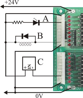
The above picture shows the two I/O connectors and three typical output devices.
Each connector contains the connections for 8 I/Os. It also has a positive supply connection labeled + and a common return labeled 0V.
In the picture A is an LED with a series current limiting resistor (plain LEDs must always have something in series to limit the current!).
B is a relay coil or solenoid. It has a diode across it to prevent inductive kick-backs from the coil. Although the board has suppression diodes onboard, we recommend external diodes to reduce noise problems. The diode can be a 1N4004 or similar 1A rectifier diode.
C is a solid state relay. Note the polarity labels.
Click here for more information on power supply distribution.
The (digital) outputs are implemented using power MOSFETs. The onboard indicator LEDs are connected directly to the output pin, and returned to the positive supply via (typically) 10K current limiting resistors.
The outputs consist of MOSFET switches between the output pin and 0V. When the output MOSFET is off, a multimeter set to DC volts connected between the output and 0V will measure a voltage slightly less than the positive supply voltage. If you set the multimeter to 200mADC, the output LED will turn on and you will get a reading of approximately V/10 milliamps, where V is the supply voltage.
Take care never to short the output pin to the positive supply voltage. If the output turns on the output device will be instantly destroyed. This includes never doing it with a multimeter set on a current range.
There are catch diodes built onto the board. This means the board will not be damaged if you are driving relay coils, solenoid valves or other inductive loads (within the ratings of the output). We nevertheless recommend external catch diodes connected directly to the coil as close to it as as possible, in order to reduce adverse effects of switching noise. The onboard diodes also mean that the load must not be connected to a supply voltage greater than the board's positive supply voltage.
The following ratings are provisional
The maximum allowable output current is 1.5A steady state, with brief (5S) peaks of 2A allowed. There is however a limit to how much total current the board can handle. This relates to the internal heating of the MOSFETS and the fact they are packed close enough to heat each other up, and to the current ratings of the connectors.
Overall you should stay within the following boundaries:
- Ambient temperature should be no more than 60°C
- The +V and 0V pins on the white I/O connectors are rated at 7A.
- The +V and 0V quick connect terminals and associated printed circuit traces are rated at 25A.
- You can have all outputs on continuously at up to 1A per output.
- You can have every other output on continuously at up to 1.5A, with the others turned off (or used as inputs)
- You can turn every fourth output on for 60 seconds at up to 2A, with the others turned off (or used as inputs)
In a typical application, driving say hydraulic solenoid valves, it would be unusual for more than a few outputs to be active at any one time.
There are 2 things to keep in mind with this:
- A semiconductor will not suddenly die if you exceed the temperature rating by a modest amount
- As a rule of thumb, every 10°C reduction in temperature doubles the life-time (halves the failure rate).
Hence, an occasional excursion to, or even above, the rated temperature isn't the end of the world. However, for long life the cooler the better.
When semiconductor switches fail they are more likely to become stuck ON than OFF.