Program your own Finite State Machine using a SPLat Controller for only $29.00.
The EC1 "EasyOne", a 32-bit fully featured SPLat Controller with USB and true multi-tasking is a easy way to learn and a cheap way to build your project.
SPLat with MultiTrack™
The SPLat controller language, and its integral multitasking operating system MultiTrack, were designed with FSMs in mind, in the context of realtime embedded machine controls. It allows FSMs to be written with all the code for a state located in one place. Below is the complete listing. I have coloured the actual FSM code for clarity.
;Define some resources. In SPLat, each kind of resource (analog/digital, input/output, etc.) ;is numbered from 0 up. The assignments here are for the EC1 experimenter's board. oHeater oEQU 0 ;A green LED on the EC1 represents the heater output oAlarm oEQU 1 ;A red LED on the EC1 represents the alarm output aiThermistor aiEQU 0 ;The thermistor is connected between analog input 0 and 0V, ;with a 10K resistor from the input to +3.3V, forming a voltage divider iReset iEQU 0 ;A push button on the EC1 board ;Get the MultiTrack tasks going. ;In this case there is only a single task, but the EC1 can have 64 tasks running at once. LaunchTask tskSampleFSM ;Add tskHeaterFSM to the "task queue" RunTasksForever ;Start the task queue running ;============= The main (and only!) task ============ tskHeaterFSM: ;-------- State 0 -------- Set0: Off oHeater Off oAlarm State0: YieldTask;Give way for other tasks to run, come back here when they are all done GoSub ReadTherm ;Get the temperature to the W floating point register fLoadQ 84 ;Get the test value to the Q floating point register fGoIfWltQ Set1 ;Compare the reading with the limit, jump (GoTo) if the reading is less GoTo State0 ;The comparison did not result in a jump, so loop back and try again ;-------- State 1 -------- Set1: On oHeater MarkTime ;Record the current system time - each task has this capability State1: YieldTask GoSub ReadTherm fLoadQ 85 fGoIfWgtQ Set0 LoopIfTiming 60000,State1 ;Back to State 1 if it's less than 600S since MarkTime was executed ;-------- State 2 -------- Set2: Off oHeater On oAlarm State2: WaitOnK iReset ;Wait for an off to on transition on the push button GoTo Set0 ;------------ Subroutine for thermistor temperature measurement, result in W register ReadTherm: fAnIn aiThermistor ;Read raw thermistor voltage to W #Thermistor Params(10000, 3840) Feed(3.3, 3.3, 10000) RangeC(0, 50) Order(5) ; °C in W
Return
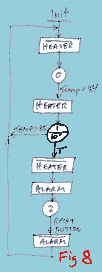
The state machine is coded within a single MultiTrack task, tskHeaterFSM. Once launched it will run forever. tskHeaterFSM contains 3 blocks of code (coloured blue), one per state. Each state contains some entry code that adjusts outputs (and possibly other stuff) just once upon entry.
In State0 we execute the entry actions to turn off the heater and the alarm. Then comes a "wait loop", a section of code that simply sits waiting for a particular condition to be met. In this case the condition being tested for is that the temperature is less than 84°C. So a subroutine, ReadTherm is called to read the temperature, then the reading is compared with the 84°C limit. If the temperature is less than 84°C the program jumps to State 1.
In State 1 the entry actions consist of turning on the heater and then capturing the current value of the 10mS system timer with a MarkTime instruction. The State 1 code then sits waiting for the temperature to rise above 85°C. However, instead of unconditionally looping back to State1 if the comparison fails, it loops only if the time limit has not expired.
If state 1 does time out, program execution "falls through" to state 2, the alarm state. The heater is turned off, the alarm is turned on, and it just sits waiting for the reset button.
Notice that the layout of this FSM code very closely reflects the state diagram![]() (with one minor difference - can you spot it?).
This is no coincidence; the SPLat language and MultiTrack multitasking operating system were designed with easy coding of FSMs as a major objective.
The simple fact that a task can yield and later resume execution at the same point in the code makes MultiTrack a "sitter" for FSM coding.
The position in the code directly reflects the position in the state diagram.
(with one minor difference - can you spot it?).
This is no coincidence; the SPLat language and MultiTrack multitasking operating system were designed with easy coding of FSMs as a major objective.
The simple fact that a task can yield and later resume execution at the same point in the code makes MultiTrack a "sitter" for FSM coding.
The position in the code directly reflects the position in the state diagram.
This is not how it works out in languages like C/C++, especially if used with a pre-emptive multitasking system. In such systems events are captured by the operating system and generate call-backs (or similar). This means the code is structured around events rather than around states. The FSM specific code must remember the context (state) by way of a state variable, and select what code to run, usually via a Switch statement, when an event is raised. The more different events and conditions that exist, the more convoluted it becomes.
If you would like to see how the same program can be coded in VB.NET, continue on. I will show you how to code an FSM in VB.NET, but it adds nothing to what I have covered so far about the actual topic of FSMs.

