In this EasyStep you get a quick overview of the standard analog inputs on the EC1
- Input range 0 to 3.3V using processor's 3.3V supply as the reference;
- fAnIn instruction gives a normalised reading 0.0 to 1.0 in floating point register W
- Accuracy: ~2.5%
- Resolution: 12 bits;
- Maximum signal source impedance: 10KΩ. Suggest 100nF ceramic across the input;
- Inputs outside 0-3.3V can upset adjacent channels or damage the chip.
An analog input is a pin that measures the voltage level of something connected to it. Whereas a digital input can only distinguish high/low voltages, an analog input returns a number that is a direct measure of the magnitude of the input voltage. This makes it useful for measuring continuously variable quantities such as (with a suitable sensor) temperature or the position of a potentiometer in a joystick.
How to drive an analog input
Analog inputs will work best if the signal source (whatever is driving the analog input) meets the following requirements:
- The voltage applied to the pin should be between 0V and the board's 3.3V internal supply voltage. Small excursions (<300mV) beyond these limits may introduce errors in other analog input readings. Large excursions can damage the board;
- The output resistance of the signal source should be as low as possible. More than 10KΩ will introduce errors;
- It is a good idea to use a 10nF ceramic capacitor between the analog input pin and 0V.
Reading the analog input in your program
When your program executes an fAnIn 0 instruction, the voltage on analog input 0 is measured, and returned as a number between 0.0 and 1.0 in the floating point register W. 0.0 corresponds to 0V in, 1.0 corresponds to 3.3V (the reference voltage).
Resolution
The analog inputs have 12-bit resolution. That means the input voltage range is divided into 2^12 (4096) steps. This corresponds to 0.806mV or 0.025% of full scale. To put this in context: With a typical thermistor temperature measurement setup it can resolve changes as low as 0.05°C (0.1°F). If you could feed it from a 1m (3') long potentiometer, it could detect movements of 0.25mm (0.01")
Accuracy
While the resolution is 0.025%, the accuracy is nowhere near that. See Analog Accuracy is expensive, Resolution is cheap The main governing factor of accuracy of any analog to digital converter is the accuracy of the reference voltage. In the EC1 the reference voltage is the 3.3V supply, which comes from a MCP1801 3.3V regulator with a worst case accuracy of 2.5% (it is typically better than that, but professionals use worst case numbers!). If you have a good digital multimeter, you can get a "fix" on the actual reference voltage by measuring between a 0V pin and a 3.3V pin.
If you need more accuracy you will have to somehow calibrate your system.
Scaling for input voltage ranges greater than 3.3V nominal
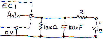
You can use a simple voltage divider to divide down the voltage into the analog input. Here's a basic circuit:

I've set the "bottom" resistor at a fixed 10KΩ, and shown a recommended 100nF ceramic capacitor for noise reduction. The value of the other resistor 'R' depends on the full scale voltage range you want to measure.
Click here for a table of values of R for different input voltage ranges.
The values given assume a worst case low reference voltage, which will ensure that the given voltage range will always fall within that range of the EC1's analog to digital converter. In practice that means the full scale voltage given will typically give a normalised reading of 0.975 rather than 1.0.
| R | Voltage range |
| 1KΩ | 3.539 |
| 1100Ω | 3.571 |
| 1200Ω | 3.604 |
| 1300Ω | 3.636 |
| 1500Ω | 3.700 |
| 1600Ω | 3.732 |
| 1800Ω | 3.797 |
| 2KΩ | 3.861 |
| 2200Ω | 3.925 |
| 2400Ω | 3.990 |
| 2700Ω | 4.086 |
| 3KΩ | 4.183 |
| 3300Ω | 4.279 |
| 3600Ω | 4.376 |
| 3900Ω | 4.472 |
| 4300Ω | 4.601 |
| 4700Ω | 4.730 |
| 5100Ω | 4.858 |
| 5600Ω | 5.019 |
| 6200Ω | 5.212 |
| 6800Ω | 5.405 |
| 7500Ω | 5.631 |
| 8200Ω | 5.856 |
| 9100Ω | 6.145 |
| 10KΩ | 6.435 |
| 11KΩ | 6.757 |
| 12KΩ | 7.079 |
| 13KΩ | 7.400 |
| 15KΩ | 8.044 |
| 16KΩ | 8.366 |
| 18KΩ | 9.009 |
| 20KΩ | 9.653 |
| 22KΩ | 10.296 |
| 24KΩ | 10.940 |
| 27KΩ | 11.905 |
| 30KΩ | 12.870 |
| 33KΩ | 13.835 |
| 36KΩ | 14.801 |
| 39KΩ | 15.766 |
| 43KΩ | 17.053 |
| 47KΩ | 18.340 |
| 51KΩ | 19.627 |
| 56KΩ | 21.236 |
| 62KΩ | 23.166 |
| 68KΩ | 25.097 |
| 75KΩ | 27.349 |
| 82KΩ | 29.601 |
| 91KΩ | 32.497 |
Some interesting ways to blow up your EC1
If you want to blow up your EC1, and void the warranty, here are some things you can do to the analog inputs:
- Connect an analog input to any voltage greater than 3.3V;
- Connect an analog input to any voltage more negative than 0V;
